LEDs
Welcome to the projects area. There will be all things related to various projects past, present and future.
Code, hints and tips can be found here along with item descriptions and uses.
Light Emitting Diodes - LEDs
LEDs emit light when an electric current passes through them.
The electrical behaviour of an LED is quite different from a normal lamp and it must be protected from excessive current lowing through it,
usually through the use of a suitable resistor connected in series with the LED.
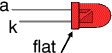
LEDs must be connected the correct way round, the diagram may be labelled a or + for anode and k or - for cathode (yes, it really is k, not c, for cathode).
The cathode is the short lead and there may be a slight flat on the body of round LEDs.
If you can see inside the LED the cathode is the larger electrode but this is not an official identification method.
Never connect an LED directly to a battery or power supply.
Testing an LED
LEDs must have a resistor in series to limit the current to a safe value, 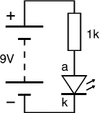 for testing purposes a 1kohm resistor is suitable for most LEDs if your supply voltage is 12V or less.
Remember to connect the LED the correct way round.
Details on how to work out what resistor is suitable is explained later.
LED Colours
The LED colours of produced by use of different semiconductor materials.
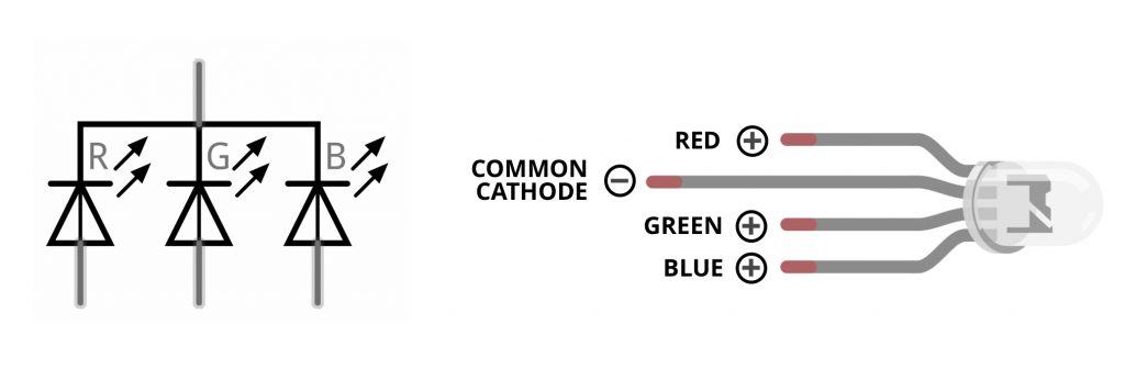
RGB LEDs
These types of LED use three seperate LEDs in one package and are individually wired with either common anode, or comman cathode.
Calculating resistor values for an LED
The maximnum current an LED passes is usually around 20mA. The forward voltage however, differs slightly according to the colour and/or semiconductor material.
| Colour |
Vf |
| Red | 1.8 - 2.1 |
| Yellow | 1.9 - 2.2 |
| Green | 2 - 3.1 |
| Blue | 3 - 3.7 |
| White | 3 - 3.4 |
The formula for calculating the required values is:
$$R = {{Vs-Vf} \over If}$$
| Key |
| R | the value required |
| Vs | the source voltage |
| Vf | the forward voltage |
| I<f | the forward current |